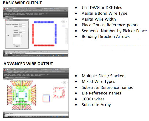
The BWX Bond Wire Exporter outputs bond wire data such as Bond wire X,Y Location, Material Type, Directional Arrows and Numbered Sequence to an XML format or CAD-ASCII data format. These outputs will contain wire bond information of polylines in a DXF or DWG vector design (see graphics at bottom of page). You may use an existing AutoCAD DWG, draft a new layout in BWX or open a DXF vector file directly into the program’s interface.
How it Works:
Stand Alone Software and Utility
for Design Suite:
The BWX software program is available
for use with Microsoft Windows as a tool
for importing DWG or DXF files for
re-design or drafting a new layout and
output of data to supported bond wire
machine. The BWX software is also
included with our
EPD
Standard Design Suite and
EPD Professional Design Suite. In
our Design Suites, the BWX is used after
the design and layout of a design made
in EPD. With the Design Suites, you may
also import DWG or DXF files into the
design for continued use and output.
How it works:
When opening an existing DWG or DXF design file, the bond wires are usually represented by artwork entities called a ‘Line’ (an AutoCAD native vector entity). If open BWX and start a new design, you may use Lines or Polylines to draft and represent the bond wires and a die outline, pads, etc.
The BWX program will allow the designer to pick individual Lines, Polylines or even Fence groups of lines to make intelligent and add the Sequence Number, Material Type, etc. BWX also has tools to create numbered Bond wire Reference blocks as single entities or within a blocked entity as nested information.
Because the design is now intelligent, it may be re-opened again in BWX for design edits such as new material, bond wire locations or sequence changes such as the profile number, Material Type, Width, etc.
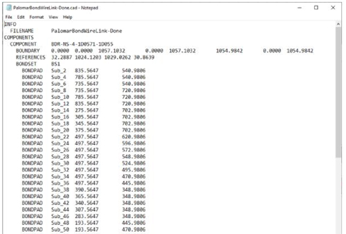
The BWX outputs the XML or .CAD (ASCII text) and sequence wire bond numbers for the selected bond wires incrementally based in user-input. These data files can be used with wire bonding machines plus other bond wire machines that accept these data formats.
Setup Tools for the Bond Wire Layout
-
Export to .CAD format in an ASCII Text file or XML format.
-
Sequence numbers and direction arrows will be visible in the drawing.
-
Multiple bond wire groups / dies can be set with unique References
-
XML data file can be used with Hesse Mechatronics wire bonding machines BJ820, BJ855, BJ935, BJ939 that accept .XML data format.
-
Create individual bondwire reference blocks.
-
Pick or Fence polyline / bond wires to set sequence numbers and bonding direction arrows for the bond diagram.
-
Assign wire types to be included in the .XML and .CAD output. Wire types can be set up to correspond to unique profiles for quick and repeat usage.
-
Update existing blocked entities such as the dies or chips with Reference points that will be included in the .XML and .CAD output.
-
Assign a name for the Bond wire reference (BDS) for the selected wires. If other bond wire blocks will be in the drawing, this attribute will allow a unique name for each.
-
Assign the Reference a Sequence Number (BDR), which controls the order in which each will appear in the exported XML and CAD file.
-
Assign a parent name (DEPENDON) to use as a reference system.
-
Set a symbol text (REFP1, REFP2) to be used as a first and second reference point.
Exporting the Bond Wire information
-
Add direction arrows and sequence numbers to the drawing and set size of text and arrow size.
-
An array of wire bond data can be exported when an array of identical parts is being wire bonded. The following parameters are available:
-
Set a Pitch of the array in the X (horizontal) dimension.
-
Set a Pitch of the array in the Y (vertical) dimension.
-
Set a Quantity of arrayed parts counted in the vertical dimension.
-
Set a Quantity of arrayed parts counted in the horizontal dimension
-
Sample CAD Output: