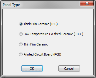
Panelizes Low Temperature Co-fired Ceramic (LTCC) or Thick Film Ceramic (THKFC) designs.
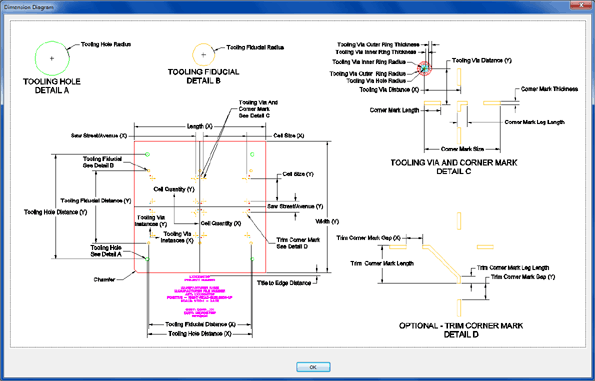
Dialog box-driven input for setting detailed and precise parameters:
- Supports standard
measurement units:
- MIL, MM, CM, INCH
-
Tooling Holes:
- Diameter – Shows the diameter of the tooling hole.
- Tol + - Shows the positive tolerance of the tooling hole.
- Tol - - Shows the negative tolerance of the tooling hole.
- X – Shows the tooling location in the X direction.
- Y – Shows the tooling hole location in the Y direction.
- General Dimensions:
- Priority Panel Size
- Cell Quantity
- Panel Length (X) and Panel Width (Y)
- Cell Length (X) and Cell Width (Y)
- Number of Columns (X) and Number of Rows (Y)
- Strip Separation Type:
- Sawn – Select for strips separated by saw.
- Scribed – Select for strips separated by scribe for scoring.
- Strip Tooling Holes:
- Diameter – Set the diameter of the strip tooling hole.
- Centerline Hole to Strip Edge (X) and (Y)
- Panel Tooling Holes:
- Diameter
- Centerline Hole to Panel Edge (X) and (Y)
- Panel Edge Dimensions:
- Side Width (X)
- Actual – Displays the actual side dimension from the panel edge to the edge of the first saw street in the X direction.
- Minimum – Set the minimum side dimension from the panel edge to the edge of the outer saw street or scribe line in the X direction.
- End Width (Y)
- Actual – Displays the actual end dimension from the panel edge to the edge of the first saw street in the Y direction.
- Minimum – Set the minimum end dimension from the panel edge to the edge of the outer saw street or scribe line in the Y direction.
- Side Width (X)
- Additional Features:
- Scribe Fiducial Gaps
- Fiducials and input values to work with the main Saw Street lines.
- Includes detailed labeled diagrams for what each input value in dialog box will affect in final output panel.
- Add extra text labels to panel.
- Save values to configuration file to be used again or shared with other users
- Plus much more...
Because of the particular and exact needs of Panelizing, CAD Design Software offers to customize the Panel Software for a design type or custom parameters for the output.
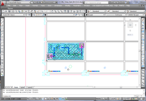
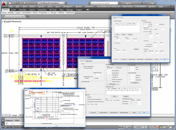
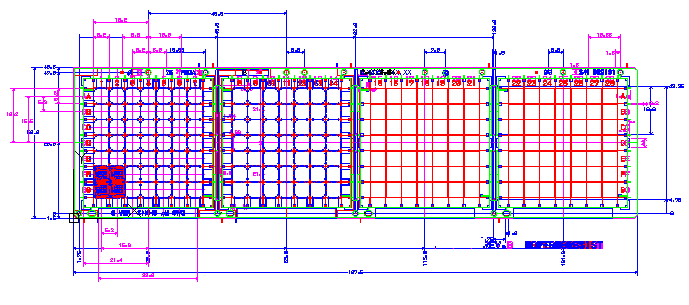
Matrix (Single Panel) – Used for creating full panel arrays utilizing saw street or scribe and snap separation lines with test coupons for the complete panel:
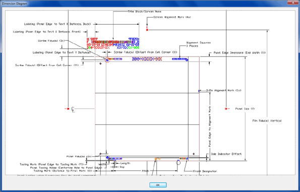
Strip (Sub Panels) – Used for creating full panel arrays utilizing saw street or scribe and snap separation lines with test coupons for each strip (column):
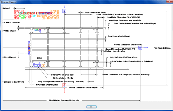
LTCC (Frame) – Used for creating Low Temperature Co-fired Ceramic panels:
