Electronics Packaging Designer or EPD is the core engine for all EPD Design Suites. This design system of LISP and ARX routines was developed in-house at CAD Design Software and was developed and used in our in-house design bureau. Over the next 25+ years of experience and interaction with our customers, we have received experience in all types of packaging and layout designs that have driven the industry.
![]()

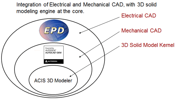
Our EPD for Windows Design (EPDWIN) Suites and our Stand Alone software products; Automated Gerber / GDS Import and Export and Bondwire Exporter, uses the AutoCAD OEM graphic engine v2019 licensed from Tech Soft 3D Inc.
The EPDWIN contains a set of standard design and drafting tools that will be similar to AutoCAD tools and are made for use with the design of layouts for the purpose in which the drafting tools are intended when purchased from CAD Design Software (e.g. design and layout tools for technologies such as PCBs, Ceramics, IC Packaging, Gerber export, etc.). When an EPD Suite or Stand Alone product(s) is executed it will load our ARX and intelligent background programs automatically.
![]()
EPD Suites allows the user to create
an intelligent drawing environment. It
loads standard design layers, design
measurement units, clearance rules, and
other default settings to use during the
design process. These settings are saved
with the drawing along with netlists and
other embedded settings. This design
standard was built to aid the user in
automatically creating layouts using a
parametric-driven design practice and
offer dynamic manipulation of design
components.
Commands such as drawing
polylines (PLINE) on EPD layers to be
recognized when running electrical
checks. Create unique or irregular
shapes for Traces, Cavities and
Boundaries to be used in the design.
Using the built-in autosnap and grid functions
allows precise
placement of parts, nodes and routing
with different angles. Routing features
include real-time DRC for trace,
terminal and via clearances.
Use EPD to create components parametrically and then place them into your designs. Parts are created by parameter input though dialog boxes, the part is placed, blocked, and saved to a library. You can also import parametric parts from our vast libraries of commonly used components. Parametrically created parts are easy to manipulate and modify as your design specifications change.
EPD contains many parametric and visual component libraries, and a highly automated design process that uses interactive routing utilities, Automatic Plane Control, LVS, and DRC. A technology system stores the material stack up, all DRC, LVS, Gerber output and all other settings made in any program that is part of the core or part of any suite. These files may be saved and reloaded for use in a future design. It includes many utility commands for use in solder mask generation, via creation, interactive routing, highlighting of nets, layer control and many other functions, etc.
Features:
-
Customized parts list generated from the schematic or layout may be automatically placed in the drawing as a table.
-
Complete ANSI standard drafting and global editing utilities are built in
-
Any number of layers possible and Unlimited pin count
-
All unit systems are supported: inches, mils, millimeters and microns
-
Eight digits of accuracy with floating decimal point (1/100,000,000 of one unit) is standard
-
Parts are placed after an automatic search of all libraries for footprints in the netlist
-
Dynamically moves parts including rats while optimizing the rats dynamically
-
Automatic creation of drill tables and hole symbols, plus storage of hole symbol selections for future reruns
-
Automatically create / read-in fabrication and assembly notes.